Execution Logic Structure Template
Introduction
An execution logic structure (ELS) template is used to create execution logic structures (ELSs) and execution logic orders (ELOs).
The grouping criteria must be defined for the valid combination of product model and grouping ID. Once the grouping criteria is defined, it must be completed in order to retrieve basic data based on the criteria. The basic data is used to define the grouping nodes of the ELS template. This functionality is further described in the following chapters.
Execution Logic Grouping Criteria
It is possible to define which attributes on a task card and subtask should be used to define the ELS. This is done by using the predefined grouping criteria available on the ELS template. The grouping criteria is made up of the following grouping elements that can be grouped, sequenced, and ordered according to your requirements.
- Execution phase ID
- Function number
- Resource ID
- Task card location
- Zone ID
The grouping criteria is defined per product model and grouping ID. The main purpose of the grouping ID is to provide flexibility on the number of grouping criteria that can be defined per product model, for instance, when you need to handle different types of maintenance visits.
To limit the amount of basic data that will be included when generating an ELS template, you can define which basic data should or should not be included when generating. This is done by enabling or disabling the Include in Execution Logic Planning option for the relevant basic data records corresponding to the grouping elements.
Following is an example of grouping criteria and how it works:
| Product Number | Model Number | Grouping ID | Grouping Description | Status |
| Fighter | F-16 | MAJ | Major Check | Active |
| Grouping Element | Group By | Sequence By | Level in Structure | |
| Execution Phase ID |
 |
1 | 1 | |
| Function Number | ||||
| Resource | ||||
| Task Card Location | ||||
| Zone ID |
 |
2 | 2 | |
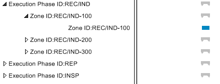
Using the data in this example we see that the grouping criteria is first grouped by Execution Phase and then by Zone. Level in Structure is used to set the number of levels on which grouping nodes are to be created. Here we see that grouping nodes will be created on two levels of the structure. Observe the graphical illustration below. The first grouping node is created for each execution phase that has the Include in Execution Logic Planning option enabled (e.g., REC/IND). The second grouping node is for the combination of valid execution phase and zone (e.g., REC/IND-100). The actual ELS node is located on the third level of the structure. When a structure level is not entered the structure will be created with just one level.

The grouping ID is status dependent. The following table shows the valid statuses for a grouping ID:
| Status | Description |
| New |
|
| Under Preparation |
|
| Active |
|
| Replan |
|
| Obsolete |
|
| Reactivate |
|
The following table shows the different menu options available for the grouping ID:
| Menu Option | Description |
| Complete Grouping Criteria | Used to retrieve basic data and create the ELS template based on the grouping criteria defined. When this option is executed, all basic data values for the grouping elements that have been selected for sequencing will be retrieved and displayed in the gantt and in a table format (i.e., in the ELS Sequencing tab and in the ELS Nodes tab). Only the basic data that has the Include in Execution Logic Planning option enabled will be considered when generating the template. |
| Redefine Grouping Criteria | Use this feature when you want to change the grouping criteria and start over. When this is done all execution logic sequencing defined for the ELS template will be deleted and the status of the grouping ID will be reset to New. |
| Copy Grouping Template | Use this feature to copy information, such as grouping criteria and sequencing from one grouping template to another. This is useful when the grouping templates are similar in their setup. |
| Remove Grouping | Used to remove an ELS template. The grouping ID, connected grouping criteria and performed sequencing will be removed. |
Execution Logic Structure Template
The ELS template is generated automatically when you perform the Complete Grouping Criteria function.
Once grouping criteria is defined and the Complete Grouping Criteria function executed, data defined in the basic data for the grouping elements which are selected to support sequencing will be retrieved. When this is done, the grouping elements will be concatenated based on the priority set by the given sequence. The generated ELS template can be viewed in the gantt or in a table format. Note: Since predecessor information cannot be set automatically, you will need to manually define predecessor information either in the gantt or in the table. You can also easily define predecessors and successors for a grouping node by using the Define Predecessors and Successors function.
Continuing with the example given above, assume that the following values have been defined in the basic data for Execution Phase and Zone:
| Execution Phase | Zone | |
| 1) | REC/IND | 100 |
| 2) | REP | 200 |
| 3) | INSP | 300 |
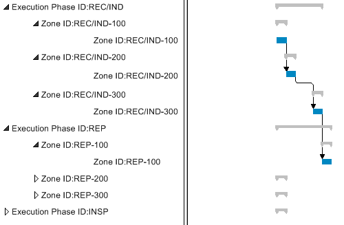
Based on the example data, the ELS template will be generated as follows. Note that an example of predecessor information that can be entered is shown in the Predecessor column in this table.
| Product Number | Model Number | Grouping ID | Grouping Description |
| Fighter | F-16 | MAJ | Major Check |
| Node ID | Grouping Node | Predecessor | |
| 1 | REC/IND-100 | ||
| 2 | REC/IND-200 | REC/IND-100 | |
| 3 | REC/IND-300 | REC/IND-200 | |
| 4 | REP-100 | REC/IND-300 | |
| 5 | REP-200 | REP-100 | |
| 6 | REP-300 | REP-200 | |
| 7 | INSP-100 | REP-300 | |
| 8 | INSP-200 | INSP-100 | |
| 9 | INSP-300 | INSP-200 | |
Through the ELS template you can set up an execution logic sequence to be the generic sequence for performing work during a maintenance visit. Once the visit has an ELS associated, all task cards and subtasks assigned to the various event codes of the maintenance visit will be assigned automatically to the relevant ELS grouping nodes within the structure.
ELS Template Gantt
Often large amounts of data will be generated in the ELS template and it can be complicated to work with a table view. In such instance, the gantt can be used to obtain a graphical view of the ELS template and to easily draw the dependencies (sequencing) between the different nodes. The gantt is made up of the navigator which can be used to view the nodes in the structure textually and the chart which can be used to get a graphical view the grouping nodes.
In the chart you will find a summary bar for the maintenance order and for each grouping node in the ELS. The summary bar for the maintenance order is shown in Black, while the summary bar for each grouping node in the structure is shown in Gray. By selecting the relevant nodes from the graphical object structure, you can expand or collapse the contents of the entire maintenance order or a certain grouping node.
Each execution logic order (ELO) node and task card in the ELS is shown as a horizontal activity bar in the Gantt. The length of each activity bar varies depending on the length of time between the ELO/task card planned start and finish dates. The color of the activity bar for a node or task card will change automatically when the status of the node or task card is changed. The applicable colors are listed in the gantt Legend. This allows you to easily view the work progress on the ELS and is useful when you want to follow up on the progress of a maintenance visit.
You can magnify or reduce the timescale using the zoom in or zoom out buttons. You can change the resolution of the gantt, i.e., the scale (whether information should, for instance, be displayed daily or weekly).
In the chart, grouping nodes are denoted by a graph bar with inverted triangles at each end while ELS nodes are denoted by a blue bar.

To create links (predecessors and successors) between the different nodes, you need to have the Create Dependencies Mode activated in the gantt. Note that any changes in the gantt will be reflected automatically in the table and vice versa.