Schema Definition
The messages required to use the Scheduling Interface are defined here in a relational schema. Each message type is shown as an entity on the schema and these are grouped into input and output message structures. The rules defining inserting, deleting and updating these entities is also defined here.
In addition to these there are definitions to internal Lookup tables and the methods for reporting interface exceptions.
The underlying physical database does not match this schema and its structure will change from release to release. The only supported features are those defined in this document. All updates to the scheduling databases must be done via IFS Scheduling applications. Any direct modifications to the database unless directed by IFS staff will invalidate your support agreement.
Introduction
The different types of entities, input, output, data and look up are defined by the following colours in the schema diagram. For clarity the schema is split into a number of diagrams the first two focusing on the key entities and the second covering security, parameters, exceptions, messages and additional attributes required for display purposes.
Data entities are those not used on the input or output of data from the scheduler but which hold other data required or collected by the scheduling applications. Some entities can belong to both Input and User categories. These are typically elements of data which are used as part of the setup and can either be input via the interface or via a data entry screen. They will be coloured as User data but on the definition the Input classification will be included.
| Data Type | Colour | Example |
|---|---|---|
| Input | Light blue |  |
| Output | Light green |  |
| Internal | Light orange |  |
| Static lookup | Light yellow |  |
| User maintained | Light pink |  |
For each entity the following will be detailed:
- Name
- Type of entity
- Description
- Notes
- Any particular Insert/Delete/Update/Select rules and conditions.
- Attributes details including name, data type, description, mandatory/optional/default values, referential constraints and processing rules to be enforced.
- Details of default rows created as part of the system setup.
Note
Updates of primary keys are not supported. Where parent entities are deleted if the relationship to the child is optional then the foreign key is nullified unless otherwise stated. If the relationship is mandatory then cascade deletes will be enforced unless stated otherwise.
Warning
Label names must all use lower case while record table entity names must be capitalised.
Note
Where attributes are specified as mandatory with no default they must be provided. If attributes are mandatory with a default value then if no value is supplied the default value is substituted. Attributes may be specified as optional with a default where there is conditional logic determining whether the value is required.
Note
All date time spans are represented in the format "P0Y0M0DT0H0M0S" or just "PT0H0M0S" for a value less than one day. For full specification of duration refer to this link:- http://www.w3.org/TR/2001/REC-xmlschema-2-20010502/#duration
Note
All date time stamps are held internally to the nearest second. Times will be accepted to milliseconds on the input but these will be truncated to be stored in the database.
Note
Any entities or attributes which should no longer be used but are still available for backward compatibility will be highlighted in grey.
Note
Data for the different namespaces cannot be mixed in the same XML document.
Schemas
The scheduling installation is over a number of schemas depending on what components have been installed. The relevant schema is shown in brackets after the entity name. Available schemas are:
| Schema Type | Description |
|---|---|
| Scheduling | Holds temporary scheduling data. |
| Modelling | Holds permanent data used by products such as the ARP. |
| Simulation | Holds data to be used in WISE simulations. |
| System | Holds permanent internal data. |
Dataset Primary Key
The schema can support multiple datasets for scheduling purposes. If more than one dataset is being scheduled the dataset should be specified on the Input_Reference. Otherwise the internal default is used, which is determined by the parameter 'DefaultDatasetId' and defaults to 'Default'.
For completeness the dataset_id is shown on all entities where it exists within this document but does not need to be specified as part of the data, it is only required on the Input Reference. Each input and output XML transaction must only relate to data within one dataset.
Where multiple organisations are defined each using their own datasets the organisation id must be specified on the Input_Reference. Otherwise the internal default '1' is used.
Deleting Objects
To delete an object already loaded into the Scheduling Schema use the Object Deletion definition. If the object does not exist then it is ignored. Please note that when deleting objects where the primary key contains a date/time or time span value these must be expressed in the XML format in the primary key string field.
When deleting data from the Modelling Database use the RAM Data Update definition.
Schema Diagrams
A number of schema entity diagrams are used to visual represent the data and relationships between the data.
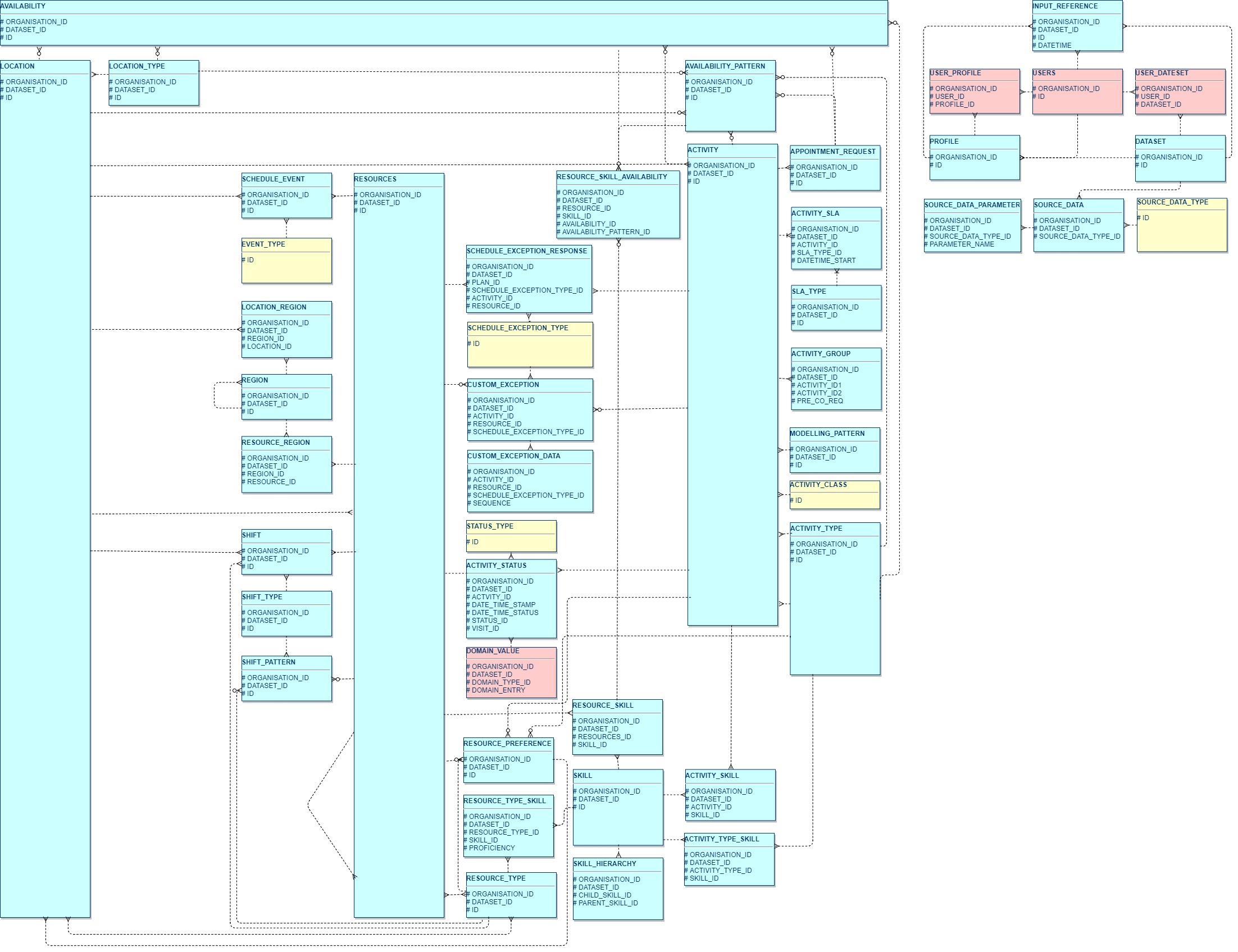
- Schema diagram 1 shows all the entities required for feeding scheduling input data into the scheduling system.
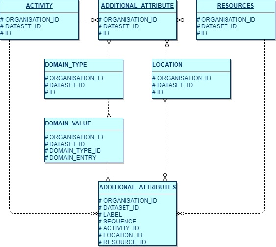
- Schema diagram 2 shows how additional attributes are used within the Scheduling Schema.
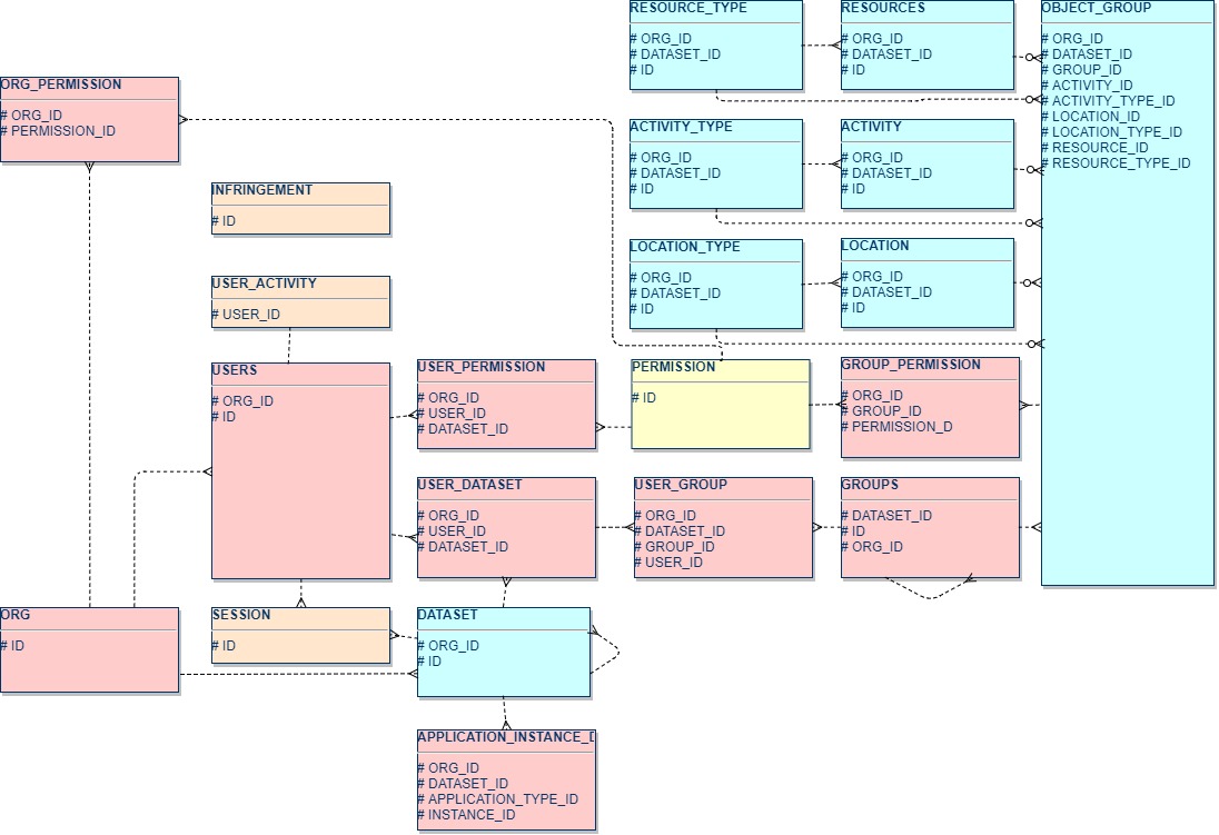
- Schema diagram 3 shows the security related entities.
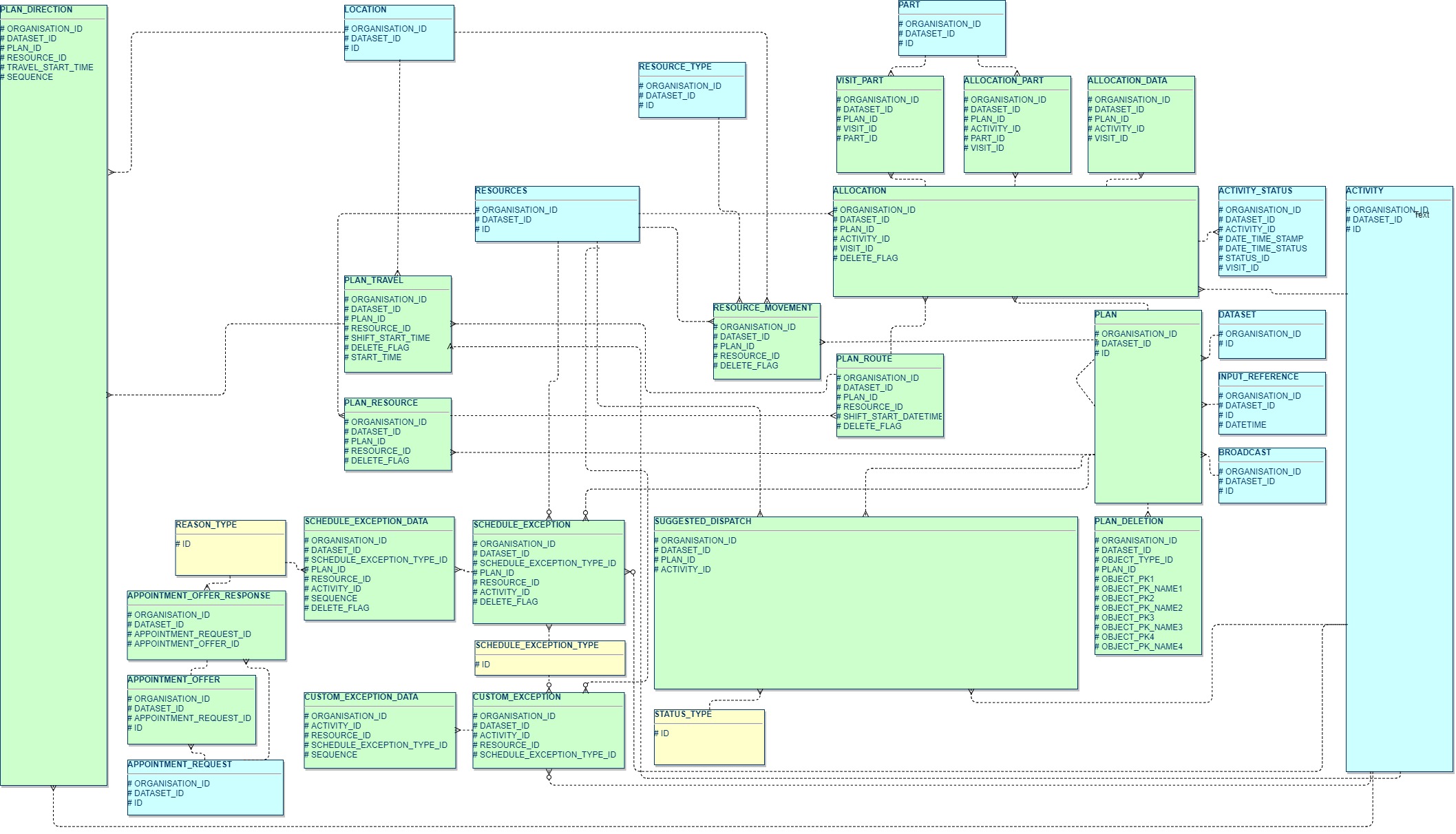
- Schema diagram 4 shows the output from the Scheduling Schema and how they relate to input objects.
- Schema diagram 5 details the required entities for supporting part constrained scheduling and depot pick-ups.
Schema Diagram 1: Scheduling Input Data
This diagram contains the main entities used for inputting data into the scheduling systems.
Schema Diagram 2: Scheduling Input Additional Attributes
This diagram shows the relationship of additional attributes to the main entities of resources, activity and location. Additional attributes are used to include non-related scheduling information for display by the Scheduling Workbench or by a 3rd party application.
Schema Diagram 3: Security
This diagram shows the related security data items for users, datasets and permissions to use functionality. This data is setup via the Scheduling Workbench and not by the interface.
Schema Diagram 4: Scheduling Output Data
This diagram shows the related entities produced by the system which define a schedule.
Schema Diagram 5: Scheduling Input Parts
This is an extension of diagram showing the input data required for parts and depot management.

Standard Interface Architecture
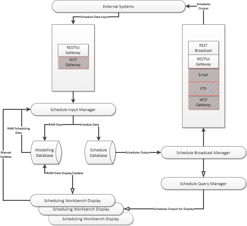
Input
Input data is passed to the scheduling system using a JSON or XML document passed to the Scheduling RESTful Gateway. All data uses UTF-8 encoding unless otherwise specified. All interface methods accept documents which conform to one of the schema definitions, and most return a result code to confirm whether the input has been transmitted successfully. For full details see the section on 'Interface Methods'.
Output
Plans produced by the scheduling system can be output to the external systems in a number of ways :
- To a REST endpoint (recommended).
- To a Microsoft WCF interface (deprecated).
- Saved as an XML document in the file system (deprecated).
- To an external web service (deprecated).
Multiple methods of output can be configured to be used at the same time each configured to send amended schedules at defined intervals of time. See Broadcast entity. Some systems do not require data to be sent externally but just require the Scheduling Workbench to be used to display and amend schedules.
For production systems IFS recommend the REST based interface using JSON.
Schema Interface
Data transmitted to and from the system via the web service is in the form of JSON or XML documents. The structure defines the data input and any return data from the system.
Validation
The scheduling software will validate the incoming data as follows:
- Test well formed JSON or XML has been passed.
- Valid attribute data types and data.
- Mandatory fields supplied and default values used automatically when null.
- Validate constraints and referential integrity.
- Validate business rules.
Scheduling Interface process
The Scheduling Schema Guide defines the data input and return data produced by the scheduling system. The interface process will consist of the following steps:
- Call the Scheduling RESTful Gateway and send an initial document containing
- Load reference data
- Load scheduling data
- Current status of activities
- Historical activity data to be displayed
- A document is returned containing
- Exceptions, errors and warnings
- A schedule plan
- Call the Scheduling RESTful Gateway and send a document containing
- Updates to reference data
- Events
- Updates to scheduling data
- A document returned containing
- Exceptions, errors and warnings
- A schedule plan / update to the previous schedule plan
Steps 3 and 4 repeat until the system is closed down, thereafter the process will start from step 1.
Note
The web service is called asynchronously. If called asynchronously then no output will be returned apart from a response indicating success or failure. Plans will be returned to a defined external web service if one or more output broadcast methods have been defined as part of the input data.
Warning
Whenever an initial load is sent into the scheduling system all previous history will be forgotten and the new load used to determine the current state of affairs. This includes the current status of activities where they have been committed to resources and the allocation of resource cannot be changed or when there has been any manual alteration to the schedules and these need to be retained on a reload of those activities.
Warning
The data within one transaction must only have one reference to a particular instance of an entity. If there is more than one instance a duplicate primary key error will be generated. One instance will be accepted the rest rejected. Which instance is accepted cannot be guaranteed. Therefore do not send duplicates within one data input transaction.
General Data Guidelines
All data passed into Scheduling system must be presented in the precise format specified in this guide for the release of the software being used. Each object used within the interface is defined in the Scheduling Schema Guide detailing each elements name, its attributes and the purpose of each. This also defines which attributes are mandatory or optional and any range of values or rules to be followed. For interfacing to the Modelling database these can be found in the Modelling Schema Guide. Definitions for entities RAM Update and RAM Update Row can be found in this guide.
As part of the Schema Guides the relationships between the various elements which form the schema are defined and presented in a set of entity relationship diagrams. These conform to industry standard definition for describing the relationships and the rules associated with each. For the data to be processed successfully these rules must be adhered to in the data.
Each set of data sent to the Scheduling system must follow these rules in addition to those specified for each element and attribute in the Scheduling Schema Guide in order for the scheduler to perform in the desired way. Data entities for the Modelling database are prefixed with 'RAM'.
Data Content Rules
- Each set of data must have one and only one
element for the scheduling database. If data is being input into the RAM database then the set of data must have one and only one element. - There must not be any duplicates of the same element within the data i.e. the primary key for an element must only occur once in the data, an
for example cannot occur more than once in the same data input. - Data not required for scheduling must not be sent for processing. A period of time is defined called the scheduling window. This is the period over which scheduling will take place. Elements such as
, , and whose start and end dates do not intersect with the defined scheduling window must not be included in the data. and should only be included if they have or within the scheduling window. Child elements must not be sent if parent elements do not exist. - All lookup data elements such as
, , , must not be sent unless they are used by an or in the schedule. can have the date and time they will be scheduled fixed externally to the system using attributes on the . If this date and time is outside the scheduling window the must not be included within the data. - The adding and deleting of the same element within the data input must be avoided since this has an adverse effect on performance. It is good practice to avoid adding and deleting elements generally particularly
and elements. These should be sent once in the initial load and changes to these avoided. To remove a from the schedule a private activity should be used instead of deleting the . These should not be changed unless absolutely necessary.
Referential Integrity Rules
The referential integrity rules as defined in the schema guide must be followed.
- Where specified the primary key must be provided for each element.
- All foreign keys provided in the data must exist within the current set of data or have been sent previously as part of the scheduling problem i.e.
cannot be referenced in the element where the element data has not been provided or an record specified for an which does not exist. Which attributes represent foreign keys to other elements in the schema are defined in the Scheduling Schema Guide. - All mandatory attributes are provided in each element.
- For some elements there are mutually exclusive optional relationships between other elements. For example an
element cannot have a foreign key to both an and a element. These constraints are shown on the entity diagrams and in the Scheduling Schema Guide. - Data marked as lookup in the Scheduling Schema Guide such as
does not need to be sent. Only entities marked as Input should be sent to the Scheduling System. - Do not delete elements such as
, , once they have been loaded if they are used by any , or respectively. - Object deletions must only be sent for objects which exist. These are objects which have been added since the last
of type 'LOAD' for the dataset the object belongs to. Object deletions place a high overhead on the system and should only be used if strictly required. To alter an existing object the revised object just needs to be sent, it does not need to be deleted and then added. - Object deletion should not be sent in the same stream as the object creation or update and should only be sent for an object which exists.
- During dynamic scheduling only send changes which have actually occurred. Do not send objects which have not changed since these will be treated as a change and cause the scheduler to re-evaluate the problem thereby slowing performance.
Syntax Rules
- All data must be presented as simple JSON or XML consisting of elements and attributes. The syntax is case sensitive and particular care must be taken ensuring the correct capitalization. See the 'Data Format' section for more details.
- Some attributes will take default values if they are not provided in the input. These are detailed in the Scheduling Schema Guide for each attribute. When sending an update to an element ensure all the attributes you want to set values for are provided.
Logical Rules
A number of elements have attributes which must be logically consistent. Where dependencies exist these are indicated in the Scheduling Schema Guide for each element. Verify that all elements conform to the rules specified in the Scheduling Schema Guide.
Common ones to be aware of are:
- Where elements have start and end dates and times the end dates and times must be after the start. This occurs on elements:
- Availability
- Shift
- Activity_SLA
- Fixing a date and time of an
to a when the resource does not have a shift at that time. - Fixing an
to a date and time in the past i.e. before element . - Fixing a resource to an
which does not have the correct or to complete the activity. - When wishing to unfix a resource from an
or the appointed date and time a null value attribute must be specified for these elements in the updated element of . - The
element contains the element and this enables the system to advance the time line within the schedule. If this is not set correctly the system can appear to stop. It must never be set to before the time on the previous . is used to define the relationship between pre-requisite or co-requisite activities. These relationships must be logically correct and non-recursive i.e. three activities linked to one another as pre-requisites must not have the first in the link also dependent on the third. - If a high proportion of activities are fixed either by resource or date and time the ability of the scheduling system to schedule activities will be severely constrained. The use of
will cause all other time constraints to be ignored. This includes SLAs. This should be avoided where possible.
System Performance
The good performance of the system is dependant on well constructed and logically consistent data being presented to it. Failure to do this will result in poorer performance than would otherwise be possible. The performance of the system cannot be guaranteed since it is dependant on a reasonable use of the interface.
Data Format
JSON
Note
The format of JSON schema data was changed in PSO 6.15+ to be consistent across the services (RESTful Gateway and Schedule Broadcast Manager) and to make better use of JSON types as specified in this section. To switch JSON formatting back to the old format the JsonFormatVersion parameter for the RESTful Gateway or Schedule Broadcast Manager can be set to 'Version 1'
Wrapper
The JSON wrapper to be used for scheduling data is:
{
  "ScheduleData": {
    .. Entity data ..
  }
}
The JSON wrapper to be used for modelling data is:
{
  "ModellingData": {
    .. Entity data ..
  }
}
Entity Data
Entity data is expressed in the following format:
"Entity_Name1": [
  {
    "attribute_name1": "attribute value",
    "attribute_name2": "attribute value"
  }
],
"Entity_Name2": [
  {
    "attribute_name1": "attribute value",
    "attribute_name2": "attribute value"
  },
  {
    "attribute_name1": "attribute value",
    "attribute_name2": "attribute value"
  }
]
Value Types
| Schema Type | JSON Format | Example |
|---|---|---|
| String | JSON String | "attribute value" |
| Integer | JSON Number | 123 |
| Double | JSON Number | 123.45 |
| Boolean | JSON Boolean | true |
| Date Time | JSON String in ISO 8601 Date Time format. When output from PSO the timezone will be UTC. | "2019-01-01T12:00:00+02:00" "2019-01-01T10:00:00Z" |
| Time Span | JSON String in ISO 8601 Duration format or JSON Number in seconds. When output from PSO the ISO 8601 Duration format is used. | "PT1H30M" 5400 |
XML
Note
It is advised to use the JSON data format where possible since this gives better performance and reduced data sizes compared to XML.
Wrapper
The XML wrapper to be used for scheduling data is:
<dsScheduleData xmlns="http://360Scheduling.com/Schema/dsScheduleData.xsd">
  .. Entity data ..
</dsScheduleData>
The XML wrapper to be used for modelling data is:
<DsModelling xmlns="http://360Scheduling.com/Schema/DsModelling.xsd">
  .. Entity data ..
</DsModelling>
Entity Data
Entity data is expressed in the following format:
<Entity_Name1>
  <attribute_name1>attribute value</attribute_name1>
  <attribute_name2>attribute value</attribute_name2>
</Entity_Name1>
<Entity_Name2>
  <attribute_name1>attribute value</attribute_name1>
  <attribute_name2>attribute value</attribute_name2>
</Entity_Name2>
<Entity_Name2>
  <attribute_name1>attribute value</attribute_name1>
  <attribute_name2>attribute value</attribute_name2>
</Entity_Name2>
Value Types
| Schema Type | XML Format | Example |
|---|---|---|
| String | XML String | attribute value |
| Integer | XML Number | 123 |
| Double | XML Number | 123.45 |
| Boolean | XML Boolean | true |
| Date Time | XML ISO 8601 Date Time format | 2019-01-01T12:00:00+02:00 |
| Time Span | XML ISO 8601 Duration format | PT1H30M |
Minimal Scheduling Data
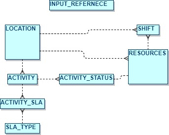
Minimal Input Dataset
A minimum amount of data must be passed to the scheduling system in order for a schedule plan to be returned. The required entities to be in the input document to achieve this are:
- INPUT_REFERENCE
- ACTIVITY
- ACTIVITY_SLA
- ACTIVITY_STATUS
- SLA_TYPE
- RESOURCE
- SHIFT / SHIFT_PATTERN + SHIFT_TYPE
- LOCATION
Each instance of a message can be presented in any order provided the document is a valid document. The order does not have to conform to the referential integrity defined in the schema, but for diagnostic purposes and to aid readability it is recommended messages are grouped logically.
The structure of the input data is as follows:
- There should be a single Input Reference record in every input. This acts as a header record and include details such as the current scheduling time, the ID of the dataset that the input belongs to and the type of scheduling required.
- For each activity that needs to be scheduled there should be an activity record, and a corresponding Location record. There should also be one or more Activity_SLA records (defining the business deadlines for carrying out the activity) and one or more Activity_Status records (defining the current status of the activity, e.g. resource is on site).
- There must be at least one SLA_Type record which can be referenced by the Activity_SLA records. This governs how the value of carrying out the activity varies over time, to ensure that business priorities are aligned with.
- For each resource able to carry out activities there must be a resources record. In addition Shift (or Shift_Pattern) records must be provided to detail when the resource will be working, and at least one location must be linked to the resource.
To initialise the scheduler for the first time the attribute Input_Reference.load_type must be set to 'LOAD'. This will stop the scheduler from processing any data it currently has for the specified dataset.
If subsequent data inputs wish to apply updates, or simply to advance the time the scheduler is working to then the Input_Reference.load_type must be set to 'CHANGE'. Any number of change files can be sent. It is strongly recommended that the changes are presented to scheduler in chronological order to ensure the best scheduling decisions are made.
Note
For full details on each of these entities and attributes please see the Scheduling Schema guide.
An example of an input document is provided below.
{
  "ScheduleData": {
    "Activity": [
      {
        "id": "1",
        "activity_class_id": "CALL",
        "activity_type_id": "Default",
        "location_id": "1",
        "priority": 2,
        "split_allowed": false,
        "do_on_site": false
      }
    ],
    "Activity_SLA": [
      {
        "sla_type_id": "SLA_TYPE_1",
        "activity_id": "1",
        "datetime_start": "2006-01-01T09:00:00Z",
        "datetime_end": "2006-01-31T17:00:00Z",
        "priority": 1,
        "start_based": true
      }
    ],
    "Activity_Status": [
      {
        "activity_id": "1",
        "status_id": 0,
        "date_time_status": "2006-01-01T09:00:00Z",
        "visit_id": 1,
        "fixed": false,
        "date_time_stamp": "2006-01-01T09:00:00Z",
        "duration": "PT5H"
      }
    ],
    "Input_Reference": [
      {
        "datetime": "2006-01-01T09:00:00Z",
        "id": "1",
        "input_type": "LOAD",
        "organisation_id": 1,
        "dataset_id": "Default",
        "schedule_data": "CONTINUOUS",
        "load_status": 0,
        "duration": "P30D",
        "process_type": "DYNAMIC"
      }
    ],
    "Location": [
      {
        "id": "1",
        "x": 402400,
        "y": 186200
      },
      {
        "id": "1000",
        "x": 382400,
        "y": 192300
      }
    ],
    "Resources": [
      {
        "id": "1000",
        "location_id_start": "1000",
        "location_id_end": "1000",
        "resource_type_id": "Default"
      }
    ],
    "Shift": [
      {
        "id": "1000_0_shift",
        "resource_id": "1000",
        "start_datetime": "2006-01-01T09:00:00Z",
        "end_datetime": "2006-01-01T17:00:00Z",
        "actual": true
      }
    ],
    "SLA_Type": [
      {
        "id": "SLA_TYPE_1",
        "revenue": 1000,
        "penalty": 1000,
        "cost": 0,
        "early_sla_benefit": 0,
        "mechanism_type": "POWER_BASED",
        "end_proportion": 0.99,
        "curve_shape": 1,
        "activity_ageing_factor": 1,
        "start_proportion": 1,
        "generate_jeopardy_exceptions": true
      }
    ]
  }
}
Requesting Output
As part of the data passed into the system either as an initial load or change, the external application can define the frequency, by what criteria and the method by which output plans are returned.
This is done by defining Broadcast messages and Broadcast Parameters in the input data. With the Broadcast you can configure:
- The minimum plan quality and / or the maximum processing time before a plan is produced.
- If a one off plan is required or one at regular intervals.
- If a Complete plan is sent, or changes since the last plan.
- The method of broadcast (to a file location, to a web service, etc.)
Note
For further information on Broadcasting plans refer to Broadcast and Broadcast Parameter in the Scheduling Schema Guide.
Output Dataset
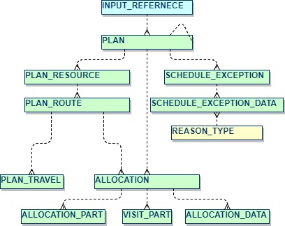
Data is passed back via a document which will contain the current scheduled plan. The entities to be in the output document are:
- PLAN
- PLAN RESOURCE
- PLAN ROUTE
- PLAN TRAVEL
- ALLOCATION
- ALLOCATION DATA
- VISIT PART
- SCHEDULE EXCEPTION
- SCHEDULE EXCEPTION DATA
- PLAN DELETION
The output data has the following structure:
- There is a single Plan record in every output, including metrics relating to the plan as a whole.
- For each resource in the plan there will be a Plan Resource record, including metrics specific to the resource.
- For each Shift belonging to the resource there will be a Plan Route, including metrics specific to the shift.
- For each Activity scheduled in the Plan Route there will be an Allocation record.
- For each period of travel on a Plan Route there will be a Plan Travel record.
- For activities which are not allocated there will still be an Allocation record but it will not be linked to a Plan Route.
- Additional allocation information is given in the Allocation Data record for each activity.
- Where parts are used, the expected usage will be shown in the Visit Part records.
- Any exceptions are detailed in the schedule exception and schedule exception data records.
- For CHANGE plan types, any deletions compared to the previous plan will be sent as Plan_Deletion rows.
An example of an output plan from the Dynamic Scheduling Engine is given below.
{
  "ScheduleData": {
    "Allocation": [
      {
        "activity_id": "1",
        "resource_id": "1000",
        "visit_id": 1,
        "activity_start": "2006-01-01T09:27:16Z",
        "activity_end": "2006-01-01T14:27:16Z",
        "visit_status": 10,
        "plan_id": 2744,
        "visit_type": "CALL",
        "date_time_fixed": false,
        "duration": "PT5H",
        "fixed_resource": false,
        "shift_id": "1000_0_shift",
        "rank": 1,
        "shift_start_datetime": "2006-01-01T09:00:00Z",
        "same_location": false,
        "allocation_source": 0
      }
    ],
    "Allocation_Data": [
      {
        "activity_id": "1",
        "visit_id": 1,
        "plan_id": 2744,
        "expected_duration": "PT5H",
        "sla_start_time": "2006-01-01T09:00:00Z",
        "sla_jeopardy_time": "2006-01-31T17:00:00Z"
      }
    ],
    "Plan": [
      {
        "id": 2744,
        "time_taken": "PT1S",
        "plan_type": "COMPLETE",
        "plan_margin": 19869.544904,
        "output_datetime": "2013-04-26T12:24:04.06Z",
        "total_allocations": 1,
        "quality": 100,
        "input_reference_internal_id": 2090,
        "total_travel_time": "PT54M32S",
        "total_travel_distance": 49114,
        "travel_type": "Lat/Long",
        "schedule_from": "2006-01-01T09:00:00Z",
        "schedule_to": "2006-01-31T00:00:00Z",
        "input_reference_date_time": "2006-01-01T09:00:00Z",
        "input_reference_id": "1",
        "average_travel_time": "PT54M32S",
        "average_travel_distance": 49114,
        "utilisation": 73.86111111111111,
        "total_on_site_time": "PT5H",
        "total_break_time": "PT0S",
        "total_private_time": "PT0S",
        "total_unutilised_time": "PT2H5M28S",
        "organisation_id": 1,
        "dataset_id": "Default",
        "broadcast_id": "Broadcast1",
        "software_version": "99.99.4833.17341",
        "allocation_type": 1,
        "profile_id": "DEFAULT",
        "load_status": 0
      }
    ],
    "Plan_Resource": [
      {
        "plan_id": 2744,
        "resource_id": "1000",
        "resource_margin": 19869.544904,
        "average_travel_time": "PT54M32S",
        "average_travel_distance": 49114,
        "total_allocations": 1,
        "utilisation": 73.86111111111111,
        "total_travel_time": "PT54M32S",
        "total_on_site_time": "PT5H",
        "total_break_time": "PT0S",
        "total_private_time": "PT0S",
        "total_unutilised_time": "PT2H5M28S"
      }
    ],
    "Plan_Route": [
      {
        "plan_id": 2744,
        "resource_id": "1000",
        "shift_id": "1000_0_shift",
        "route_margin": 19869.544904,
        "average_travel_time": "PT54M32S",
        "average_travel_distance": 49114,
        "total_allocations": 1,
        "utilisation": 73.86111111111111,
        "shift_start_datetime": "2006-01-01T09:00:00Z",
        "shift_end_datetime": "2006-01-01T17:00:00Z",
        "shift_overtime_end": "2006-01-01T17:00:00Z",
        "total_travel_time": "PT54M32S",
        "total_on_site_time": "PT5H",
        "total_break_time": "PT0S",
        "total_private_time": "PT0S",
        "total_unutilised_time": "PT2H5M28S"
      }
    ],
    "Plan_Travel": [
      {
        "plan_id": 2744,
        "resource_id": "1000",
        "shift_id": "1000_0_shift",
        "distance": 24557,
        "end_time": "2006-01-01T09:27:16Z",
        "start_time": "2006-01-01T09:00:00Z",
        "start_location_id": "1000",
        "end_location_id": "1",
        "activity_id": "1",
        "visit_id": 1,
        "shift_start_datetime": "2006-01-01T09:00:00Z"
      },
      {
        "plan_id": 2744,
        "resource_id": "1000",
        "shift_id": "1000_0_shift",
        "distance": 24557,
        "end_time": "2006-01-01T14:54:32Z",
        "start_time": "2006-01-01T14:27:16Z",
        "start_location_id": "1",
        "end_location_id": "1000",
        "previous_activity_id": "1",
        "visit_id": 1,
        "previous_visit_id": 1,
        "shift_start_datetime": "2006-01-01T09:00:00Z"
      }
    ]
  }
}
Minimum Dataset Schema
Input
Output
Times and Time Zones
This section contains some explanatory notes relating to how times and time zones are handled within PSO.
DateTime attributes
For DateTime attributes, the standard xml DateTime format includes information about the time zone offset from UTC, and this should be included on any DateTime values sent in the input data.
2022-07-22T12:30:45-05:00
In this way, each DateTime references an exact point in time, and as such there is then no need for any separate time zone information to be included in the data.
'Time of Day' attributes
Some schema entities require that a time of day be specified. In this case the time of day will be speficied in 'TimeSpan' format, so for example 9 hours (PT9H) represents 9am.
Some example uses of this in the Scheduling Schema are on the Availability_Pattern, Shift_Pattern, and Appointment_Template_Item tables.
If these are used then it is also necessary to specify the time zone that the data is to being used in. In each case, this can be specified as a separate 'time_zone' (or occasionally 'time_zone_id') attribute on the table. (For Appointment_Template_Item the time_zone attribute it on the parent 'Appointment_Template' table).
The time_zone attribute can be specified in either windows or IANA formats. For example, the New York time zone can be specified as either 'America/New_York' (IANA format) or 'Eastern Standard Time' (Windows format).
Note
Although the time_zone attribute is optional in each case, it is strongly recommended that a value is set. If no value is set then the services will use the local machine time zone, which will be UTC for cloud based systems.