Overview Diagram Reference
Overview diagrams represents a logical structure of entities and the relationships among them. Each entity represents an object that is a natural part of and is important to the business and its business processes. Overview diagrams give us an overview of the relationships among these business objects.

Figure:
Overview Diagram toolbar
Overview Diagram toolbar contains different tools to modify and add artifacts to the Overview Diagram.
-
 Create New Entity
Select button and click on an empty diagram area to create a new Entity and add to the Diagram
-
 Add Existing Entity
Select button and click on an empty diagram area to add an existing Entity to the Diagram
-
 Create Utility Logical Unit
Select button and click on an empty diagram area to add a Utility Logical Unit
-
 Add Existing Utility
Select button and click on an empty diagram area to add an existing Utility to the Diagram
-
 Create Reference
Select button and draw a Reference link between two Entities in the diagram
-
 Create Parent Association
Select button and draw a Parent Association link between two Entities
-
 Create Dependency
Select and draw a Dependency link between two Entities or between an Entity and a Utility LU
-
 Create Based-On Link
Select and draw a BasedOn link between two Entities
-
 Add Note
Adds a Note by selecting and clicking on an empty area in the diagram
-
 Add link from Note
Select and draw a Note link between a Note and another diagram object
Context Menu Options Available In Overview Diagram Objects
Entity
-
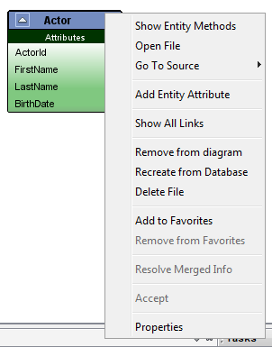
Entity
-
Show Entity Methods
Fetch and display entity database methods under the diagram node. Methods are not shown by default. For methods get displayed relevant entity should be already deployed in the connected database.
-
Open file
Opens the model file [EntityName].entity in the model editor
-
Go To Source
The sub-menu lists the generated source files related to the Entity
-
Add Entity Attribute
Adds a new Entity Attribute to the Entity
-
Show All Links
Creates all links related to the entity in the diagram
-
Remove from diagram
Removes the entity and links to and from the object from the diagram. The entity model file will not be removed.
-
Recreate from Database
Recreates the entity with the database published information.
-
Delete File
Deletes the [EntityName].entity file related to the entity. Also removes the diagram object and the associated links.
-
Add to Favorites
Adds the Entity into My Artifacts of the project.
-
Remove from Favorites
Removes the entity from the projects My Artifacts.
-
Resolve Merged Info
Resolve a diagram object which was merged using 'Merge Rose Information' Diagram Context Menu option.
-
Accept
User can check differences between overview diagram and a model file in the disk by selecting
'Diff Overview Diagram' RMB menu option of the overview file in the project explorer.
When the diff is created you can accept the entity node to the new overview diagram. i.e. accepting the selected entity node to the new overview diagram.
-
Properties
Bring into view the Properties window of the IDE.
Entity Association (Reference and Parent)
-
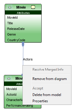
Entity Association
-
Resolve Merged Info
Resolve a diagram object which was merged using 'Merge Rose Information' Diagram Context Menu option.
-
Remove from diagram
Removes the link from diagram. The associated model will not be deleted.
-
Delete from model
Removes the Association model from the Entity. Also removes the link from the diagram.
-
Properties
Bring into view the Properties window of the IDE.
Entity BasedOn Link
-
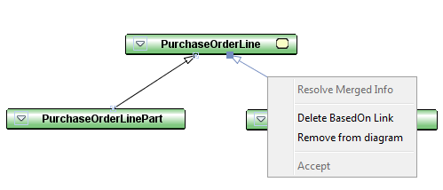
Entity BasedOn Link
-
Resolve Merged Info
Resolve a diagram object which was merged using 'Merge Rose Information' Diagram Context Menu option.
-
Delete BasedOn Link
Removes the [basedOn] property from the Entity. Also removes the link from the diagram.
-
Remove from diagram
Removes the link from diagram. The [basedOn] property of the Entity will not be cleared.
Entity Attribute
-
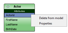
Entity Attribute
-
Delete from model
Removes the Attribute from the Entity.
-
Properties
Bring into view the Properties window of the IDE.
Utility Logical Unit
-
Utility Logical Unit
-
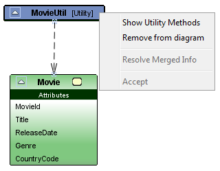
Show Utility Methods
Fetch and display list of database methods of the utility package under the diagram node. Methods are not shown by default. For methods get displayed relevant utility package should be already deployed in the connected database.
-
Remove from diagram
Removes the node and links drawn to and from the node form the diagram.
-
Resolve Merged Info
Resolve a diagram object which was merged using 'Merge Rose Information' Diagram Context Menu option.
Dependency Link
-
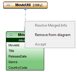
Dependency Link
-
Resolve Merged Info
Resolve a diagram object which was merged using 'Merge Rose Information' Diagram Context Menu option.
-
Remove from diagram
Removes the link from the diagram.
Note
-
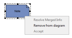
Note
-
Remove from diagram
Removes the node and links drawn to and from the node form the diagram.
-
Resolve Merged Info
Resolve a diagram object which was merged using 'Merge Rose Information' Diagram Context Menu option.
Note Link
-
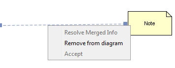
Note Link
-
Remove from diagram
Removes the link form the diagram.
-
Resolve Merged Info
Resolve a diagram object which was merged using 'Merge Rose Information' Diagram Context Menu option.
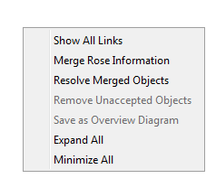
Diagram Context Menu
-
Diagram Context Menu
-
Show All Links
Creates all links related to the all entities in the diagram
-
Merge Rose Information
Merge information from .cat file which were not added during reverse engineering. For example 'based on' relationships which were not shown when reverse engineering will be shown through Merge Rose Information.
-
Resolve Merged Objects
Resolves the merged objects (From Merge Rose Information) to the diagram.
-
Minimize All
Minimizes all the nodes in the diagram
-
Expand All
Expands all the nodes in the diagram
Adding Existing Entities From a Project
To add an Existing Entity within the same project:
-
Open the Overview Diagram you wish to add the Entity to.
-
Select the Entity in the project navigation structure.
-
Drag and drop the Entity from the project navigation structure to an empty area in the diagram.
-
To add multiple Entities: select Entities in the navigation structure while CTRL key is pressed and drag and drop onto the diagram
Modification of Entity properties
Properties of an Entity, Entity Attribute and Entity links such as Reference/Parent Association/BasedOn can be modified through property sheets of each diagram object. To show the property sheets of a given diagram object you can choose the 'Properties' menu option in the Context menu of each diagram object type.
Please note that an Entity can be modified through the Overview Diagrams only if:
-
The Model File related to the Entity is open in the Developer Studio Editor area.
-
And if the model file related to the Entity is not read only.
Missing Entities and Associations
Entities that represent Entity model files that are not currently available in the local disk or the model cache of the Database are marked in red. The links associated to these missing entities are also shown in red. In the case these Entities have been permanently deleted, users should take steps to delete these redundant diagram objects from the Overview Diagram by selecting the context menu action 'Remove from diagram'.
Invalid Links between Entities
Links of type Reference and Parent Association are denoted in red if these association types do not specify the correct Association Attributes in the property sheets. Association attributes are automatically mapped when drawing links of above types if attributes by the same name exist for the key columns of the participating Entity. However if no such matching attributes exist, users need to manually set them through the associations property sheet.
Entity State Machine Indicator
Entities that contain state machines are denoted with a special icon in their header section in the Overview Diagrams.
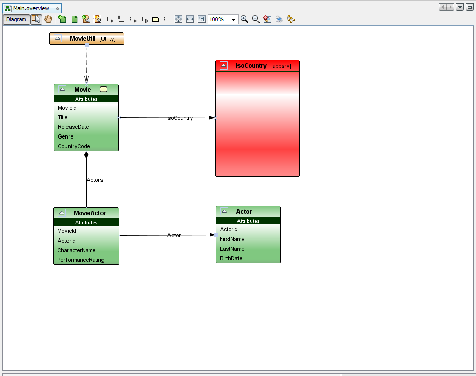
Figure:
Overview Diagram Example
This page is generated from IFS Developer Studio at 2021-08-13 08:40.