Configuration hierarchies for assemblies
The structure of an assembly is defined by the hierarchy of the configuration slots created under the assembly.
The hierarchy of configuration slots represents the assembly's functional and physical equipment hierarchy. Once the configuration hierarchy is defined, you can identify the part numbers that can be installed in specific physical locations on the assembly, define maintenance program requirements, create job card definitions, and more.
When breaking down an assembly into configuration slots that represent its systems and components, it is recommended to use a reference standard, such as the ATA Chapter breakdown. You can use the ATA Chapter reference numbers as the codes you assign to configuration slots.
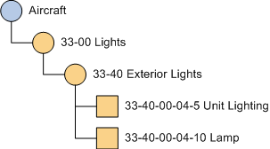
The following diagram shows a hierarchy of configuration slots under the aircraft, in which the ATA Chapter references have been used in addition to a name for each configuration slot. The configuration slots 33-00 Lights and 33-40 External Lights represent functional systems of the aircraft, whereas the two configuration slots below 33-40 Exterior Lights represent components that are installed in the exterior lighting system.
Figure: Configuration slot hierarchy

Configuration classes
Every configuration slot has a configuration class, which determines the level of detail and the information Maintenix maintains for the parts assigned to the configuration slots. Because Maintenix behaves so differently from one configuration class to another, you cannot change the configuration class that is assigned to a configuration slot.
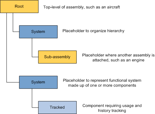
The following diagram shows how the configuration classes are used in the configuration hierarchy:
Figure: Configuration classes in the assembly hierarchy

| Config class | Description |
|---|---|
| ROOT |
When you create an assembly, a corresponding root configuration slot is created. This is the top-level configuration slot in the assembly hierarchy. When you create a root slot, an ACFT or ASSY part group is automatically created. |
| SYS |
System configuration slots are used to group other configuration slots that make up a functional system of the assembly, such as several tracked configuration slots that make up the air conditioning system. They do not correspond to physical components and they do not have part numbers associated with them. You create system configuration slots under root or other system slots. Do not create system slots under tracked or sub-assembly slots. The common hardware (COMHW) and the tools and service equipment (TSE) assemblies cannot have system subconfiguration slots. When you create a system slot, no part group is automatically created. |
| SUBASSY |
A sub-assembly configuration slot is where another assembly (sub-assembly) plugs into the current assembly (parent assembly), for example where an engine is installed on an aircraft. A sub-assembly can have multiple positions per parent. For example, a SUBASSY slot for an engine can have four positions. You create sub-assemblies under system configuration slots. You cannot create sub-configuration slots under sub-assembly configuration slots. The hierarchy of the sub-assembly is defined in the separate assembly that you create to model that component. To determine which assembly fits into a sub-assembly configuration slot, Maintenix matches the part number assigned to the SUBASSY configuration slot to the part number assigned to the ROOT configuration slot of the sub-assembly. You cannot create a sub-assembly configuration slot under the common hardware (COMHW) or the tools and service equipment (TSE) assemblies. When you create a sub-assembly slot, an ASSY part group is automatically created. |
| TRK |
Tracked configuration slots are used for high-value
components that have the following requirements:
You create tracked configuration slots under system or other tracked configuration slots. A tracked slot can have multiple positions per parent. When you create a tracked slot, a TRK part group is automatically created. |
In addition to the part groups that are created automatically for configuration slots, you can create additional part groups, on any configuration slot, including system (SYS) slots. You might want to create additional part groups for all untracked part numbers that are specific to a configuration slot. Untracked part numbers are those that have the inventory classes of serial-controlled (SER), batch-controlled (BATCH), or kit (KIT). Note that consumables that are used on many configuration slots or many assemblies should not be included in part groups on configuration slots, but rather in the common hardware assembly so that they can be added to any task.
Mandatory configuration slots
When you create a configuration slot, you specify whether it is mandatory. If a component is removed from a mandatory configuration slot, the hierarchy is considered incomplete (not airworthy) until a replacement component is installed. Missing mandatory components are displayed as errors on the Preview Release page.
If a new sub-assembly or tracked configuration slot is added to an assembly when inventory for the assembly already exists, an empty hole is created on the existing inventory (holes are not created if system slots are added). If the new configuration slot is mandatory, the assembly is marked as incomplete.
When inventory already exists, it is best to create new configuration slots as non-mandatory, create and install the appropriate inventory, and then edit the configuration slot to make it mandatory. An easy way to verify whether any inventory exists for a specific assembly is to consult the Assembly List tab - beside each assembly, a check box indicates if inventory exists in the system.
When a transaction occurs that could change whether a component is marked as complete, Maintenix automatically evaluates impacted inventory and sub-components for completeness. You can manually trigger an evaluation of completeness for aircraft inventory by clicking the Evaluate Completeness button on the Inventory Details page.
Positions on configuration slots
- As two separate configuration slots; one configuration slot for the left main landing gear and another configuration slot for the right main landing gear.
- As a single configuration slot with two positions: left and right.
Modeling as separate configuration slots allows positional control over configuration and maintenance, whereas modeling as a single configuration slot with multiple positions does not.
For example, if the left and right main landing gear require different part numbers—part A only fits on the left side, and part B only fits on the right side—this configuration is enforced by using separate configuration slots for the left and right positions. A single configuration slot with two positions cannot enforce the configuration; part A could be installed in either the left or right position, and likewise for part B.
Maintenix keeps track of which part number and serial number is installed in each configuration slot and position. Mechanics must specify the configuration slot and the position every time they record a component installation or removal.
Part incompatibility rules can be defined for assembly positions.